Cathedral Ceiling Insulation
Cathedral Ceiling Insulation
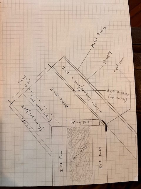
I am building an ICF house (Basement and main floor ICF to the level of eaves). It will have a cathedral ceiling with an open half loft. I have read the “Cathedral Ceilings that Work” article what I was thinking about doing is basically a modification of “Assembly #1” as laid out by that article.
What I would like to do is have a complete thermal envelope of the house where the ICF walls, gable end walls, and roof sheathing create the envelope. I read an article about a house being built this way and watched an accompanying YouTube video a while back but I didnt save it and I can not find it for the life of me now. But basically they used Zip Sheathing which came right to the corner of the ICF zero overhang on gable or eave walls. All seams were taped and everything was insulated inside to create a super tight thermal envelope. Then above that 2x4s were placed on edge (with long timberlocks down into the rafters through the zip) to create both an air gap and the overhang framing for proper overhangs.
Another major difference from the “Assembly #1” is that I was thinking of using Dense Pack rather than fiberglass batt.
The third difference is that “Assembly #1″ uses 2x4s gusseted onto the main rafter for a deeper cavity. Rather than do this. I was thinking that if I used a 2×6 and sistered it onto the side of the rafter, (overlapping 1.5”) rather than in line with the rafter with plywood gussets, and used dense pack it would effectively create a thermal break because insulation would be stepped over the edge of the main rafter and behind the add on extension if that makes sense.
Am I missing any reason why this wont work well?
Attaching a drawing for clarity. Drawn approximately to scale where 1 graph block=1 inch
GBA Detail Library
A collection of one thousand construction details organized by climate and house part


Replies
How far are you? Have you started construction on the ICF? I have a similar build - the ICF, siding, standing seam steel roof are complete. Certainly learned a bunch of lessons...
I think overall your idea of monopoly framing and continuous envelope at the roof sheathing is a good one. I am concerned that I don't see any rigid insulation over top of the roof deck. How will you prevent sorption of moisture into the cold Zip sheathing from below?
I have the ICFs started, the basement is poured and the first couple courses of the main floor before I ran out of time before winter. I have 4 remaining courses of ICF to go as soon as the weather turns (Vermont) then...everything else.
It is my understanding that because there is a clear air gap from eaves to ridge vent over the sheathing that no rigid would be needed. Moisture can escape to ridge vent above the thermal envelope. Correct me if I am misunderstanding this building principal.
The moisture you're thinking about is above the sheathing, but as I am typing this I just checked and now realize that Zip is vapor permeable (I do really wish that I had used it on my house). Malcom's point below, is about a vapor retarder between your conditioned space and the underside of the sheathing (the issue I was bringing up in my first reply). Keeping vapor away from the sheathing is one solution, although another is to keep that sheathing warm.
These are a couple of other links you might peruse for details:
https://buildingscience.com/documents/digests/bsd-102-understanding-attic-ventilation
https://buildingscience.com/documents/guides-and-manuals/irc-faqs/irc-faq-conditioned-attics
With respect to ICF, I realized as things moved forward that details in the transition between materials is challenging and unfortunately that my original contractor was did not pay much attention to detail. We had some issues before the roof was finished with water intrusion along the ICF wall in at least one location. I suspected the water got behind the foam, then went through the cold joint, capillary action (between concrete pours) to the inside. Putting Tyvek over the exterior surface of the ICF dealt with nearly all of this; the rest was remedied confidently after adding the steel/overhangs. After putting up the Tyvek, I would suggest shingling a strip of Grace or other water/ice barrier from the top of the Zip/sheathing over onto the Tyvek covering the ICF. In my experience, the intersection of concrete, foam, lumber/rafters, and roof sheathing in combination with the angle and exposure make this an important detail. Another consideration is liberal use of a fluid applied barrier, such as Zip Liquid Flash or Prosco R-Guard.
Think about how you want your eaves and rakes to look, and how you will provide structural stability. The 2x4s we used between the roof sheathing and the steel were laid flat and on a diagonal. They did extend out past the exterior wall, to support the overhangs, but we also had 'applied' rafter tails below/exposed to add quite a bit of support. Placing the 2x4s on their spine, as I think you indicated in your detail sketch, would add more strength as they extend in the overhang, but it may make them much harder to secure to the roof deck.
Dustin,
" I have a similar build - the ICF, siding, standing seam steel roof are complete. "
Photos please!
Ward,
Your assembly will work well.
- The one thing I don't see is an interior air barrier/vapour retarder under the t&g ceiling.
- To reduce complexity I'd consider going with I joists for the roof framing. The wider top chord also makes it easier to hit with the fasteners through the 2"x4"s above.
- You will have much the same amount of thermal bridging whether you align or offset the 2"x6". If you want to reduce it I would use 2"x3"s and gussets, with a space between the rafter and 2"x4".
- Another alternative is to use 2"x12"s with either an inch of foam board on the underside, or 1 1/2" strips of foam on the bottom of the rafters.
Dustin, I find it interesting you are used Tyvek over ICF. This is the first I have seen or heard of this anywhere on an ICF build. I do see how it could be a cheap and effective drainage plane as the ICF are not 100% waterproof but they are close enough to waterproof that once the roof (with overhangs) is complete and siding of virtually any type is applied they would be as waterproof as anyone should need. Sounds like your issue was before the roof was complete though?
Malcom, correct me if I am wrong but I did not think a vapor barrier was needed for Dense Pack Cellulose, I was under the understanding that it acts as its own vapor barrier and that adding a barrier below it (on the warm side) can actually cause issues with trapped moisture rather than help. I am no expert but I have seen this in several sources.
On your comment "or 1 1/2" strips of foam on the bottom of the rafters." can you explain what you mean further? Do you mean that you'd apply a strip to the bottom of each rafter then the 2x4" extension in line with the rafter with gussets across the assembly? So basically the way its shown in the article for "Assembly #1" but with a strip of foam between the rafter and additional piece?
Ward,
The problem with interior vapour-barriers is that in warm climates where air-conditioning is used, they can trap moisture in the cavity. That's not the case with vapour-retarders.
Cellulose isn't a vapour-barrier or retarder. It buffers moisture, and is more forgiving than batts when it accumulates, but still benefits when you limit the amount of moisture it has to deal with.
Dense-packed cellulose is also better at stopping air-currents than batts, but all permeable roof insulation benefits from a warm side air-barrier/vapour-retarder to limit the amount of moist interior air that makes its way up the the sheathing - especially when you use Zip, which is quite low perm, slowing it's path to the vent channel above. Painted drywall usually serves that function on ceilings, but with t&g I think it would be prudent to add a dedicated variable-perm membrane detailed as an air-barrier.
The 1 1/2" of foam would be in strips attached to the bottom edge of each rafter, with no framing below it. Much like a Bonfiglioli wall, it would do two things: Limit thermal bridging, and add depth the the 2"x12"s to give you a comparable amount of cellulose in the cavities. It would make attaching the t&g more difficult.